2022
This walkthough is one of a number which help to illustrate the principles of ARM SoC design:
| ASIC version | Introductory ASIC version <= |
| FPGA version | Introductory FPGA version |
| Altera FPGA version | Introductory Altera FPGA version |
While the first three versions include examples of custom interface hardware typical of a System-on-Chip design, the "Introductory" version(s) include non-specific input and output ports in the manner of a microcontroller system. While the use of custom interface hardware is likely to yield better results (if it doesn't yield better results you will probably be better off using a microcontroller rather than an SoC), the use of non-specific input and output ports can aid understanding and can offer a starting point for the design of custom interface hardware.
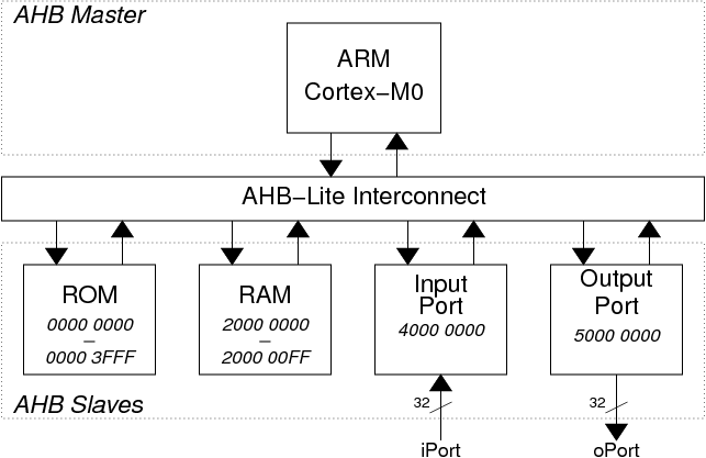
A very simple ARM System on Chip has been designed:
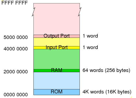
The secondary images are an artefact of the partial address decoding which only uses the top 4 address bits (HADDR[31:28]) in order to decide which slave is being accessed.
In order to build the ARM SoC, we need SystemVerilog files to model the hardware plus 'C' program files and other support files to build the software. Further files are required to support simulation:
    mkdir -p ~/design/system_on_chip/example_asic_introductory
    cd ~/design/system_on_chip/example_asic_introductory
init_soc_asic_introductory_example -here
Running the compile_and_link script:
    cd software
    ./compile_and_link
should create a Verilog hex format file named "code.hex"
which could be used in simulation but not in ASIC synthesis and a "code.vmem" version of the same hex data which is better suited to ASIC synthesis.
    cd ..
    ./simulate &
(The xmverilog command to run the simulation is:
    xmverilog +gui +access+r \
              +tcl+testbench/arm_soc.tcl \
              -y behavioural +libext+.sv \
              +define+prog_file=software/code.hex \
              +define+prog_file_vmem=software/code.vmem \
              testbench/arm_soc_stim.sv
but it's easier to use the simulate script)
Note that because the stack grows downwards, the higher memory addresses are used before the lower ones.
The key to system-on-chip design is the creation of custom interface hardware.
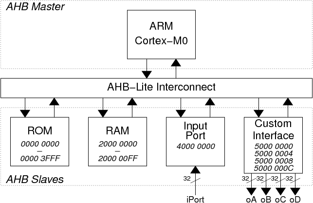
A modified ARM System on Chip including a simple custom interface is to be designed:
The file name for the interface should be ahb_custom_interface.sv and it should be placed in the existing behavioural/ directory.
A template for the custom interface can be found here: ahb_custom_interface.sv
You will need to take the template and fill in the code where it is missing. You can base the code that you enter on the code from the output port module: ahb_output_port.sv. Since the custom interface supports more than one address, you will need to add code to generate a word_address signal during the address phase. An example of this sort of code can be found in this example module: ahb_switches.sv
The file name for the top-level module should be arm_soc_custom.sv and it should be placed in the existing behavioural/ directory.
You can base the new module on the existing SoC module code: arm_soc.sv.
Changes that you should make are:
Note that there is no need to change the interconnect module (ahb_interconnect.sv) because the new interface occupies the same area of the memory map (0x5000000-0xFFFFFFFF) as was previously occupied by the output port.
The testbench/ directory already includes a arm_soc_custom_stim.sv testbench file to test the new system. The command to use is:
./simulate testbench/arm_soc_custom_stim.sv &
If all goes well, the behaviour of the new system will match that of the old one since the the 'C' program is unchanged. The only difference is that the the output values are being written via oA rather than oPort.
Now modify the 'C' program to access the other registers in the custom interface.
Changes that you should make are:
// Define the raw base address value for the custom interface

#define AHB_CUSTOM_BASE                         0x50000000

// Define a pointer with correct type for access to 32-bit registers
//
// The the four registers in the interface can then be accessed as:
//    CUSTOM_REGS[0]
//    CUSTOM_REGS[1]
//    CUSTOM_REGS[2]
//    CUSTOM_REGS[3]

volatile uint32_t* CUSTOM_REGS = (volatile uint32_t*) AHB_CUSTOM_BASE;
After each change you should recompile the code then re-run the simulation and check that the new behaviour is as you expect.
Having completed this lab walkthrough, you should have a basic understanding of SoC design including an ability to build a simple custom interface and write a 'C' program to access the interface.
At this stage you can experiment with other changes to the system but you should try to make only small changes between simulations to increase the chances of being able to debug the system.
Iain McNally
18-3-2022