2022
This walkthough is one of a number which help to illustrate the principles of ARM SoC design:
| ASIC version | Introductory ASIC version |
| FPGA version <= | Introductory FPGA version |
| Altera FPGA version | Introductory Altera FPGA version |
While the first three versions include examples of custom interface hardware typical of a System-on-Chip design, the "Introductory" version(s) include non-specific input and output ports in the manner of a microcontroller system. While the use of custom interface hardware is likely to yield better results (if it doesn't yield better results you will probably be better off using a microcontroller rather than an SoC), the use of non-specific input and output ports can aid understanding and can offer a starting point for the design of custom interface hardware.
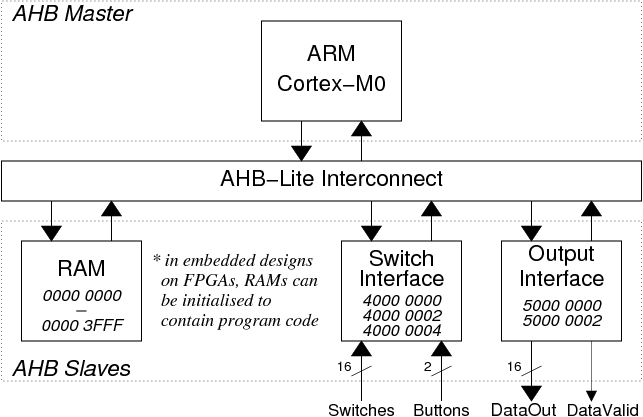
A very simple ARM System on Chip has been designed:
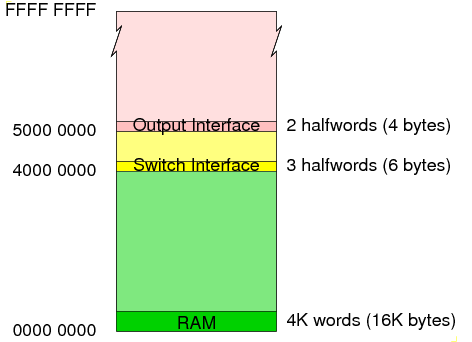
The secondary images are an artefact of the partial address decoding which only uses the top 4 address bits (HADDR[31:28]) in order to decide which slave is being accessed.
In order to build the ARM SoC, we need SystemVerilog files to model the hardware plus 'C' program files and other support files to build the software. Further files are required to support simulation:
SoC design is a blend of hardware design and software design including third-party components such as microprocessor cores and library software and custom components such as custom interfaces and application software. When looking at the custom components, there is often a trade-off to be made between undertaking a particular task in hardware or software. Some tasks may be easily carried out in hardware leading to simplified software while other tasks may be more easily carried out in software leading to simplified hardware.
In this example we have two custom interface modules which have been designed to integrate with the external world (in this case just switches, buttons and LEDs) and simplify the software:
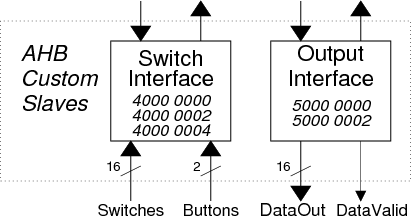
The switch interface (ahb_switches.sv) allows numbers to be entered via 16 switches and two buttons.
In order to enter a number, the user will set up the binary number on the switches and then press one of the buttons.
The aim of the interface is to avoid the processing of unwanted/false data - for example, changing the switch input from 3 to 4 may involve the following transitions:
  0000 0000 0000 0011	(3)
  0000 0000 0000 0111	(7)
  0000 0000 0000 0101	(5)
  0000 0000 0000 0100	(4)
including two unwanted/false data values (7 and 5).
By introducing a button for number entry, we can ensure that only valid numbers are entered. By introducing a second button it allows us to enter two different 16 bit numbers using only 16 switches.
Based on this requirement, we might design an interface containing two registers:
In this case we would have no way to distinguish a series of numbers: 5,7,3 entered via Button[0] from a longer sequence including repeats: 5,7,7,7,3,3.
The more sophisticated approach used here includes a third register containing status information combined with a handshaking protocol which is typical of a lot of custom interface harware:
This allows the processor to see if there is new data available, simply by checking one of the bits in the Status register.
Note that this interface does not deal with switch bounce. If switch bounce is perceived to be a problem, we could include software which might ignore duplicate data entered in quick succession. Alternatively debouncing hardware could be added to the switch interface.
The output interface (ahb_out.sv) allows data values and error status (data validity) information to be displayed via LEDs.
The aim of the interface is to ensure that the data and the data validity information is always in sync.
Based on this requirement, we might design an interface containing two registers:
With this simple approach we have a problem that, whichever register is updated first, we will have a few clock cycles where the DataValid value doesn't correspond to the DataOut value (e.g. if the DataOut register is updated first, there will be a few cycles when the old DataValid value and the new DataOut value exist together). While this is not a problem if the output is going to some LEDs it will often cause a problem if the output is driving some other circuit. For this reason this interface is designed such that DataOut and DataValid change on the same rising clock edge.
To support this operation, we will have two addressable registers (these are the registers that are visible to the programmer):
and a third register which is not addressable:
In order to output a data value, the programmer will write a bit to the NextDataValid register to specify the vailidity of the next data and then write the data itself to the DataOut register. The writing of the DataOut register will trigger a copy of the NextDataValid register to the DataValid register thus ensuring that the two outputs are always in sync:
        DataOut <= HWDATA;
        DataValid <= NextDataValid;
In common with many custom interface circuits, this interface also supports a Status register which allows the programmer to see the current status of both the DataValid and NextDataValid bits.
The memory-mapped registers in these custom interface circuits have a variety of features:
The DataOut register in the output interface can be read or written.
The SwitchData registers in the input interface can be read but not written. The same goes for the Status registers in either interface.
The NextDataValid register in the output interface can be written but not read.
Writing to the DataOut register in the output interface has the side effect of changing the DataValid register and the Status register. Similarly reading from a SwitchData register in the input interface has the side effect of changing Status register.
When you design your own custom interface circuits you should think about the access requirements and access side effects for the memory-mapped registers.
    mkdir -p ~/design/system_on_chip/example_fpga
    cd ~/design/system_on_chip/example_fpga
init_soc_fpga_example -here
Running the compile_and_link script:
    cd software
    ./compile_and_link
should create a Verilog hex format file named "code.hex"
which can be used in simulation and synthesis.
    cd ..
    ./simulate &
(The xmverilog command to run the simulation is:
    xmverilog +gui +access+r \
              +tcl+testbench/arm_soc.tcl \
              -y behavioural +libext+.sv \
              +define+prog_file=software/code.hex \
              +define+prog_file_vmem=software/code.vmem \
              testbench/arm_soc_stim.sv
but it's easier to use the simulate script)
In order to synthesise the system onto an FPGA development board you will need a top level "wrapper" file and a matching constraints file:
| FPGA Vendor | wrapper file | constraints file | |
|---|---|---|---|
| Nexys 4 | Xilinx | nexys4_wrapper.sv | nexys4_wrapper.xdc |
| DE0 | Altera (Intel) | de0_wrapper.sv | DE0.qsf |
| DE1-SoC | Altera (Intel) | de1_soc_wrapper.sv | DE1_SoC.qsf |
| DE2 | Altera (Intel) | de2_wrapper.sv | DE2.qsf |
| DE2-115 | Altera (Intel) | de2_wrapper.sv | DE2-115.qsf |
Iain McNally
18-3-2022