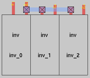
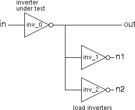
All but the simplest of designs are based on the re-use of cells through the use of hierarchy. In this walkthrough we will create a new hierarchical design called inv_ld which will contain an inverter loaded with two other inverters (n.b. inv_ld is short for INVerter LoaDed so the second to last character is an L not a 1).
First change to the directory containing the inverter cell and then start magic as follows:
    cd ~/design/magic/test
    magic -T c35b4 inv_ld &
Since the cell inv_ld does not exist, it is created
by magic.
![]()
The first inverter is placed using the :getcell inv command.
This inverter is labeled inv_0 by magic.
![]()
Move the box cursor immediately to the right of the newly placed cell
![]() and repeat the getcell command to place a second inverter, inv_1.
and repeat the getcell command to place a second inverter, inv_1.
![]()
Move the box cursor to the right of the second inverter and place a
third inverter, inv_2.
![]()
![]()
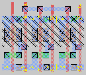
Type :expand or use the appropriate macro
to see the contents of the selected cell.
![]()
Place the box cursor such that is surrounds the whole design and repeat the
expand command to see the contents of all three cells.
![]()
You can undo this with the :unexpand command. For more information on this and other related commands see the magic tutorial on cell hierarchies.
Lastly use polysilicon and metal1 wiring to join the cells and add
line labels in & out and point labels
n1 & n2.
Note that the new polysilicon wiring is a deeper red than the original
indicating that it is part of the cell being edited rather than part of
one of the sub-cells.
![]()


Save your work and quit from magic
   :save
   :q
To check the design, type
check_magic_cell -T c35b4 -M 1 inv_ld
from the unix prompt. Note that previously, to check inv.mag, you used check magic_leaf_cell. This is not suitable here since inv_ld.mag contains sub-cells (i.e. it is not a leaf cell). For more details see the Checking Magic Cells web page.
The circuit you have created will be used to characterize the inverter with the analogue simulator HSpice. An HSpice simulation of the inverter inv_0 is more realistic when it is driving other gates. Note that when we plot waveforms from HSpice, we are interested in the input: in and the output: out of the inverter under test (not the outputs: n1 & n2 from the load inverters).

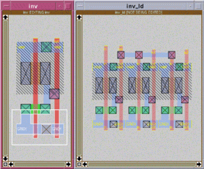
When the inverters are placed, we are placing instances of the one master inverter. If the master is changed then all instances will show that change. This can be seen in action using the following procedure:

A list of the magic macro commands can be found in the file $CAD_HOME/lib/magic/sys/.magicrc.
The full Magic Tutorials are avialable on-line.
You should read Magic Tutorial #4: Cell Hierarchies for more complete coverage of hierarchy in magic.
You may also like to look at Magic Tutorial #5: Multiple Windows which provides more information about about commands used for window manipulation (you can ignore the section on Colour Editing).
The manual page for magic is also available on-line. Type the following at the unix command prompt:
man -s 1 magic
Iain McNally
13-10-2021