DFT version
RTL Synthesis using Design Compiler
Learning Outcomes:
After completing this unit, you should be able to:
- Set up the DC RTL Synthesis Software and run synthesis tasks
- Synthesize a simple RTL design
- Create your own scripts
- Carry out basic timing and power analysis based on the results
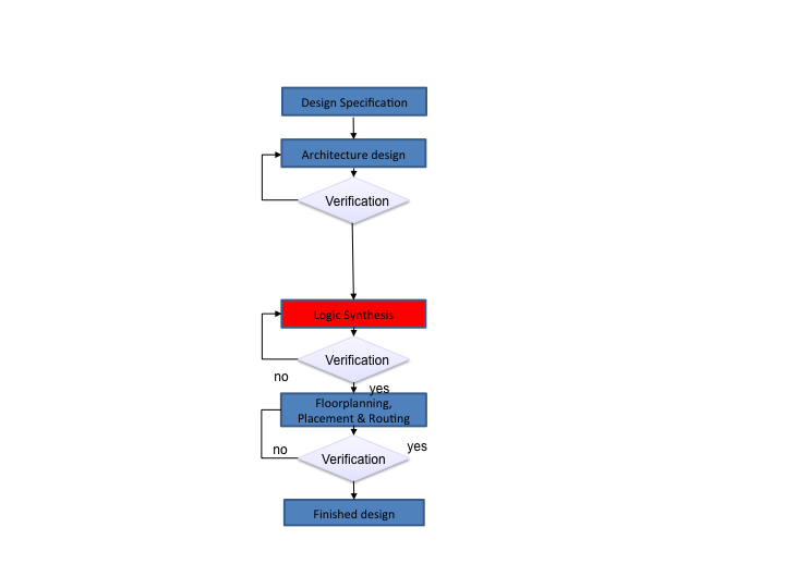
Digital Design Flow
Design Compiler Lab Instructions
For this lab you will need:
- A synthesizable Verilog of the design (this is provided)
- Library Setup File (this is provided)
Synthesis Process
Design Directory Management
- Create a directory for your digital design project (e.g. ~/design/ams/ams_demo)
- Inside this directory create sub-directories called
behavioural, constraints and gate_level.
Copy your hdl design files into the behavioural directory.
- Also create a sub-directory for your synthesis files and call it synthesis.
You need to save the library setup file ".synopsys_dc.setup" in this folder.
note that you will probably have to rename this file as it is likely to have
been saved without the first "."
(alternatively if you run the command do_c35b4_copy_synopsys_setup from within the synthesis directory
this should copy the setup file and give it the correct name).
ams_demo
________________________|______________________
| | | |
behavioural constraints gate_level synthesis
How to setup Linux Environment to run DC
- Move into synthesis directory and type the following command:
dc_shell -gui
If you are logged into one of the Redhat 6 CAD servers (cadteaching, hart2 or hind2)
the dc_shell command should already be in your search path and this command
should run without any error messages (do not run any DC_Setup script).
If the .synopsys_dc.setup file is in the current working directory,
the 0.35 um AMS technology library will automatically be loaded when dc_shell is invoked
(there is no need to explicitly source any library setup file).
Read in the HDL
Presto compilation completed successfully.
1
Elaboration
- Elaboration is the stage where the design is translated into a series of graphs, which can then be mapped onto an optimal structure
- The basic command is very simple:
elaborate <modulename>
- In this case you need to type:
elaborate wrap_qmults
- Open a schematic window in order to see the circuit that has been created:
- Schematic -> New Design Schematic View
Add Constraints
- You can use constraints to control the action of the compiler.
- Constraints describe the surrounding environment of the circuit, such as loads and drives of IO, and clock characteristics.
- By default, Design Compiler will not constrain any paths. If you issue the command:
check_timing
- You will get the following output
Warning: the following end-points are not constrained for maximum delay.
End point
---------
complete
........
overflow
result_out[1]
result_out[0]
........
Add Constraints: Defining the clock
- Most of the paths can be constrained by defining a clock.
- Example: Create a clock called "master_clock", applied to the input port "Clock", with a period of 20 ns with the following command:
create_clock -period 20 -name master_clock [get_ports Clock]
Keep adding constraints until there are no more warnings.
Add Constraints: Optimize Area
- set_max_area: This constraint specifies the maximum area a particular design should have. The value is specified in units used to describe the gate-level macro cells in the technology library.
- Example: to minimise the design area, we issue the commands
set_max_area 0
This will instruct design compiler to use as little area as possible.
Synthesis
Specifying the ports for Scan path insertion
This tells the which ports to use for the scan path control signals:
set_dft_signal -view existing_dft -type ScanClock -port <clock_port> -timing {5 15}
set_dft_signal -view existing_dft -type Reset -port <nreset_port> -active_state 0
set_dft_signal -view spec -type ScanEnable -port <test_port> -active_state 1
set_dft_signal -view spec -type ScanDataIn -port <sdi_port>
set_dft_signal -view spec -type ScanDataOut -port <sdo_port>
For the qmults example the following ports should work:
set_dft_signal -view existing_dft -type ScanClock -port Clock -timing {5 15}
set_dft_signal -view existing_dft -type Reset -port nReset -active_state 0
set_dft_signal -view spec -type ScanEnable -port Test -active_state 1
set_dft_signal -view spec -type ScanDataIn -port SDI
set_dft_signal -view spec -type ScanDataOut -port SDO
Scan path insertion
create_test_protocol
dft_drc
set_scan_configuration -chain_count 1
preview_dft
insert_dft
Design Analysis
- We can apply a range of analysis capabilities to our design to check that
it meets our requirements.
- To get a quick summary of the design performance and area statues we can use
the command
report_qor
This will provide information about the timing information, critical path slack,
critical path clock period, total design area and information about the CPU statistics.
Design Analysis: Power Report
- To get a quick summary of the design power statues we can use the command
report_power
This will provide information about dynamic and leakage power.
Design Analysis: Timing
- To report the timing of the design. we can use the command
report_timing
By default, the report_timing command displays information on the critical path or the timing path with the maximum delay.
- To examine the critical path graphically
- In design vision: go to the Schematic menu and choose the option Add Paths From/To
- Fill in the starting point and end point of the critical path from the previous timing report
- Click ok
- Click ok again for the pop up window
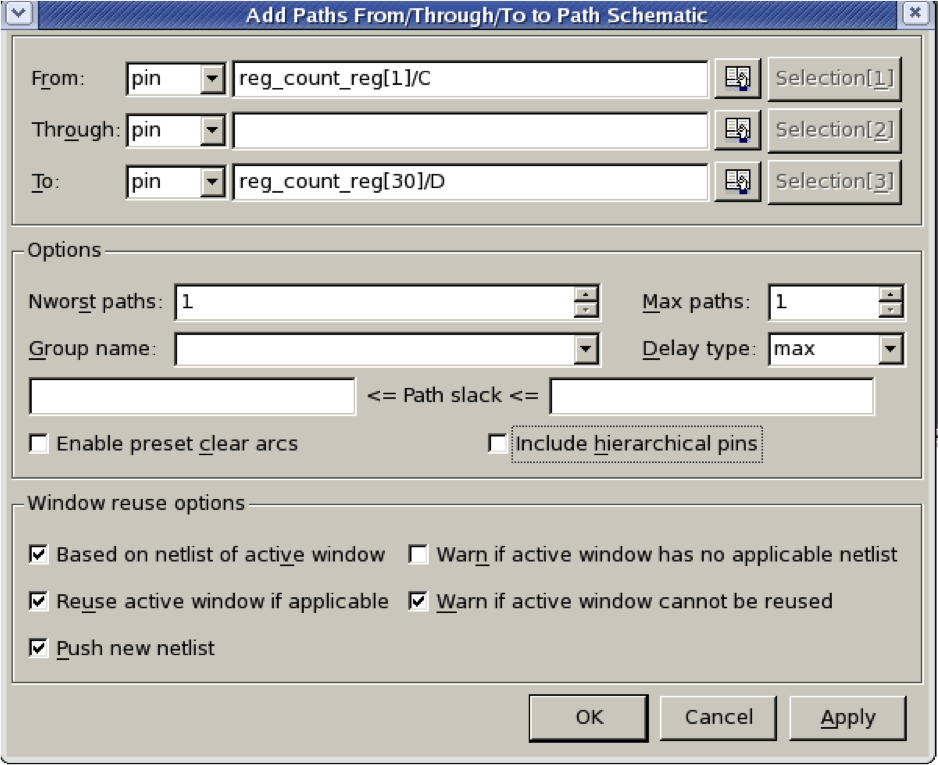
This will generate a graphical view of your critical path:
Design Analysis: Save Reports
- You can output the report to a file using:
report_area > synth_area.rpt
report_power > synth_power.rpt
report_timing > synth_timing.rpt
Timing Optimization
- Optimise the performance of the design as follows:
- Change timing constraints to target higher clock frequencies
- Use the techniques provided in appendix 1 to meet your target performance
- Repeat the above process several times until you reach the maximum achievable frequency
- Estimate area and power of the design for each target frequency
- Make sure your design is free from Hold time violation (refer to appendix 1)
Fix Naming
It is important to ensure that the naming styles of variable in the design are
appropriatefor the target output language we are using (Verilog in this case).
We can firstly see what names need changing:
report_names -rules verilog
If we are happy with the proposed new names we can perform the name changing process:
change_names -rules verilog -hierarchy -verbose
Save Out the Design:
This is the final step in the synthesis flow, it allows the designer to transfer the
synthesised circuit to the next stage of the design flow. This can be done as follows:
- 1. For Place and Route Stage: You need to save the following files:
- 2. For post synthesis simulation: You need to save the following files:
The easy way…
- Rather than type all these commands in each time, they can be stored in a
simple script text file and run with the appropriate design name in each case.
- Simply click on the non-graphical window with the "dc_shell" prompt
and type in:
Using Design Vision
- Using the GUI you can also simply load the script described previously into
the command line of the GUI
Simple Script
analyze -format verilog "../behavioural/qmults.sv ../behavioural/wrap_qmults.sv"
elaborate wrap_qmults
create_clock -name master_clock -period 20 [get_ports Clock]
compile
report_area > synth_area.rpt
report_power > synth_power.rpt
change_names -rules verilog -hierarchy -verbose
write -f verilog -hierarchy -output "../gate_level/wrap_qmults.v"
write_sdc ../constraints/wrap_qmults.sdc
write_sdf ../gate_level/wrap_qmults.sdf
exit
Discussion Points
- What is the maximum frequency you can achieve?
Can you optimise the design further? Explain how
- How does optimizing design performance affect its area overhead?
- How does optimizing design performance affects its energy dissipation?
- How can you resolve hold time violations?
Appendix 1: Optimization using synthesis tool
There are many ways in which a designer can tweak the design at the
synthesis stage to obtain the target performance :
- Compilation with map_effort high option
- Register balancing
- Removing Hierarchy
- Choosing High-Speed Implementation for High-level
Compilation with map_effort high option
- Using a map_effort high option during the first synthesis run is not advisable as
the run-time for a map_effort high option is significantly longer than that for a
map_effort medium.
- Generally, during synthesis, it is advisable for the designer to run a quick
synthesis on the design using a map_effort medium option when employing
design constraints. This would allow the designer to have a feel for the timing
violations if any exist.
- Example:
compile -map_effort high
Register Balancing
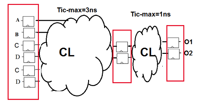
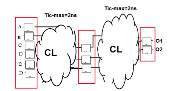
- Register balancing is a very useful command when it comes to optimizing
designs that are made up of pipelines.
- The concept here is to allow Design Compiler to move logic from one stage of
the pipeline to another. This would allow Design Compiler the flexibility to
move logic away from pipeline stages that are overly constrained to pipeline
stages that have additional timing.
- You can balance the register after you compile by typing:
balance_registers
|
=> |
|
|
Removing Hierarchy
Choosing High-Speed Implementation for High-level Functional Module
- The designer can manually change the implementation selection specified synthetic library cell instances by setting the variable set_implementation as follows:
set_implementation <implementation_type> <cell_list>
If A1 is an instance of the DW01_ADD cell in the current design, a cla carry-lookahead implementation can be specified to implement A1
set_implementation cla A1
Implementation type | Description |
rpl | Ripple carry |
cla | Carry look ahead |
clf | Fast carry look ahead |
sim | Simulation model |
The set_implementation command does not function on cell instances that are
not defined in a synthetic library.
To list the current implementation of all synthetic library instances:
report_resources
To remove any effects of set_implementation from all synthetic cells of the
current design:
remove_attribute [get_cells *] implementation
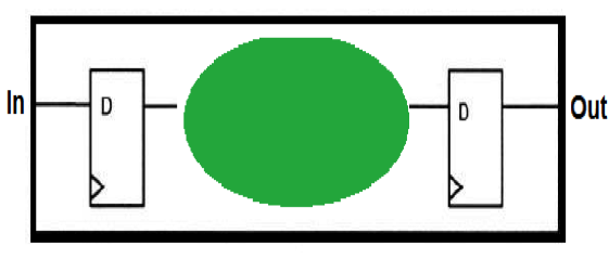
How to Fix Hold Time Violation