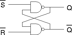
The Xcelium digital simulator will simulate the behaviour of a digital circuit provided that a SystemVerilog HDL model file exists for that circuit. The creation of such a model file is described elsewhere; this page describes the simulation process assuming that the model already exists.
Because of it's complexity, SystemVerilog is best described by example. We will consider the simulation of a number of simple circuits starting with an RS flip-flop:
 |
The SystemVerilog HDL model file for this circuit is rs_flipflop.sv. |
The following file, rs_flipflop_stim1.sv, is a simple stimulus file for the RS flip-flop:
// stimulus file for RS flip flop

module rs_flipflop_stim;

timeunit 1ns; timeprecision 10ps;

logic notR, notS;
wire Q;

  rs_flipflop rs_instance1 ( Q, notR, notS );

  // stimulus information

  initial
    begin
        notR = 1; notS = 1;
      #1000
        notR = 0;
      #1000
        notR = 1;
      #1000
        notS = 0;
      #1000
        notS = 1;
      #1000
        notR = 0;
      #1000
        notR = 1;
      #1000
	$display("\n                    Simulation complete\n");
        $finish;
    end

  // probe information

  initial
    begin
      $display("                Time     Inputs    Outputs");
      $display("                       notR  notS     Q");
      $display("                ====   ==========  =======");
      $monitor($time,"     %b    %b       %b", notR, notS, Q);
    end

endmodule
Inputs to the model under test are declared as registers.
Outputs from the model under test are declared as wires.
The stimulus information section contains a single "initial begin end" construct containing a number of input signal assignments "signal = X" and a number of time delays "#xxxx".
All inputs are initially defined, after which an input need only be mentioned when it changes.
The last command within the construct is always "$finish;".
The stimulus information section includes a "$display();" system task which is used to inform the user of the status of the simulation - in this case Simulation Complete.
The "$monitor();" system task causes changing values to be displayed in text form. The formatting string
" %b %b %b"controls the format for display of the three arguments that follow (each is in binary and separated by the appropriate number of spaces).
The "$monitor();" system task is preceded by a number of "$display();" tasks which provide header information making the text output easier to read.
Download the SystemVerilog source files into a suitable directory (e.g. ~/design/verilog/lab/simulation) and type the following at the unix command prompt:
xmverilog rs_flipflop_stim1.sv rs_flipflop.sv
or
modelsim_batch rs_flipflop_stim1.sv rs_flipflop.sv
The simulator output is in the form of a value for Time, notR, notS and Q printed each time that one of the inputs or outputs changes. It should look something like this:
                Time     Inputs    Outputs
                       notR  notS     Q
                ====   ==========  =======
                   0     1    1       x
                1000     0    1       0
                2000     1    1       0
                3000     1    0       1
                4000     1    1       1
                5000     0    1       0
                6000     1    1       0

                    Simulation complete
Try both simulation commands and check that you get the same result with each.
Although a simple stimulus file exercises the design and allows us to see the results, it does not tell us if the design is working. A new version of the stimulus file, rs_flipflop_stim2.sv, adds automatic verification and tells us if the design is working or not:
// stimulus file for RS flip flop

module rs_flipflop_stim;

timeunit 1ns; timeprecision 10ps;

logic notR, notS;
wire Q;
integer errors;

  rs_flipflop rs_instance1 ( Q, notR, notS );

  // stimulus information

  initial
    begin
        errors=0;
        notR = 1; notS = 1;
      #1000
        notR = 0;
      #1000
        assert ( Q == 0 ) else
          begin errors=errors+1; $display("ERROR with Q"); end
        notR = 1;
      #1000
        assert ( Q == 0 ) else
          begin errors=errors+1; $display("ERROR with Q"); end
        notS = 0;
      #1000
        assert ( Q == 1 ) else
          begin errors=errors+1; $display("ERROR with Q"); end
        notS = 1;
      #1000
        assert ( Q == 0 ) else
          begin errors=errors+1; $display("ERROR with Q"); end
        notR = 0;
      #1000
        assert ( Q == 0 ) else
          begin errors=errors+1; $display("ERROR with Q"); end
        notR = 1;
      #1000
        assert ( Q == 0 ) else
          begin errors=errors+1; $display("ERROR with Q"); end
        if (errors == 0)
	  $display("\nSimulation Passed\n");
        else
	  $display("\nSimulation Failed\nError count = %d\n",errors);
        $finish;
    end

  // probe information

  initial
    begin
      $display("                Time     Inputs    Outputs");
      $display("                       notR  notS     Q");
      $display("                ====   ==========  =======");
      $monitor($time,"     %b    %b       %b", notR, notS, Q);
    end

endmodule
errors is declared as an integer and set to zero at the beginning of the stimulus. Whenever an error is found, this error count value is incremented. If the error count is zero at the end of the simulation, then the simulation was successful.
The output Q is checked against a known correct value. The sequence "notR = 0; #1000 assert ( Q == 0 )" activates the reset for the flip-flop (this flip-flop has an active-low reset signal named notR) then waits for 1000 nanoseconds for the result to settle before checking that the output is reset to zero. Where the result doesn't match the expected value, the error count is incremented and an error message is displayed.
Download the new stimulus file and execute the simulation command:
xmverilog rs_flipflop_stim2.sv rs_flipflop.sv
When an error is flagged during automatic verification there are two possible sources:
In fact there is a mistake in the rs_flipflop_stim2.sv file. Identify and correct this mistake and then re-run the simulation.
The two simulators used so far, Xcelium and ModelSim, each provide a graphical user interface (GUI) for waveform display. This lab will cover the use of the SimVision GUI for Xcelium and the ModelSim GUI.
Run the command
xmverilog +gui +access+r rs_flipflop_stim1.sv rs_flipflop.sv &
The SystemVerilog files rs_flipflop_stim1.sv and rs_flipflop.sv are first checked for syntax errors then converted into an internal format and finally linked together ready for simulation. This process is known as compilation and elaboration.
If the compilation and elaboration is successful, the +gui option causes the SimVision GUI to be opened to control the final simulation stage and to view the resulting waveforms. Note that the +access+r option ensures that SimVision is granted read access to the simulation database. Without this access permission, no waveforms could be displayed.
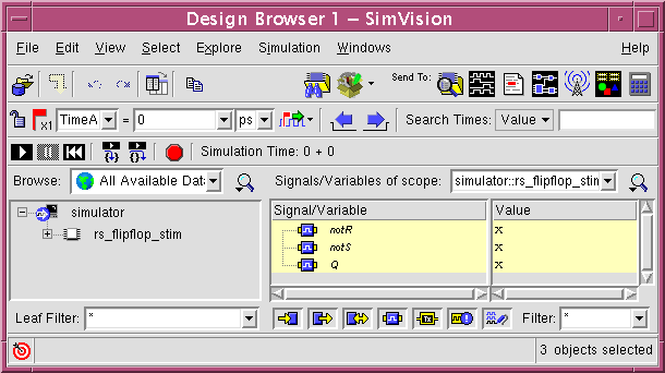
If all goes well you should find you are presented with two new windows, the SimVision Console and the SimVision Design Browser:
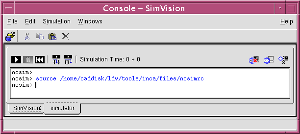
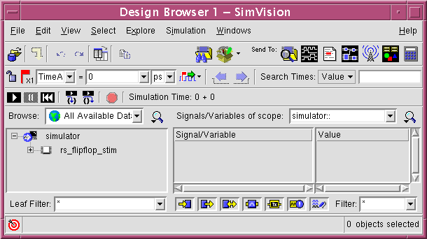
Select the rs_flip_flop_stim instance:
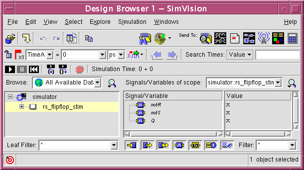
Select all three signals in the Signal/Variable section of the window:
Click the waves icon,
![]() , to send the selected signals
to a waveform viewer window.
, to send the selected signals
to a waveform viewer window.
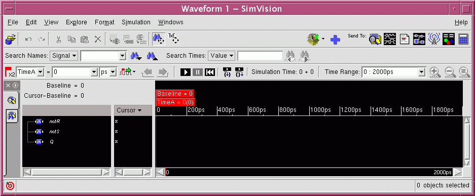
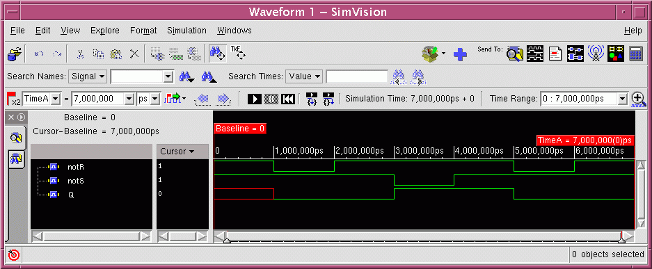
Click the play icon,
![]() ,
to run the simulation to the first breakpoint (in this case the terminating
$finish; command) and then click the full view icon,
,
to run the simulation to the first breakpoint (in this case the terminating
$finish; command) and then click the full view icon,
![]() , to show the complete waveforms:
, to show the complete waveforms:
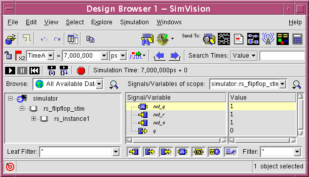
Expand the rs_flipflop_stim instance in the browser window by selecting the
 sign from
  .
Then select the newly visible rs_instance1 instance and then the not_q
signal within that instance:
Click the waves icon,
![]() , to send the selected signal
to the waveform window.
At this stage no waveform is visble for not_q signal since it was
not probed when the simulation was run:
, to send the selected signal
to the waveform window.
At this stage no waveform is visble for not_q signal since it was
not probed when the simulation was run:
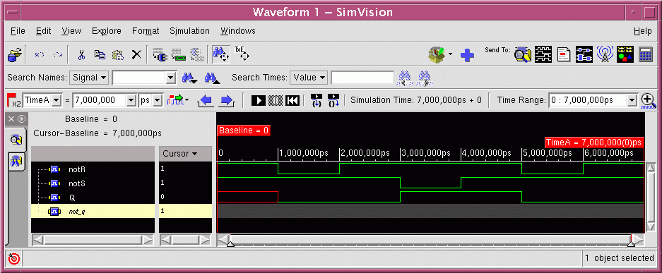
Click the rewind icon and then the play and full view icons,
![]()
![]()
![]() , to re-run the simulation:
, to re-run the simulation:
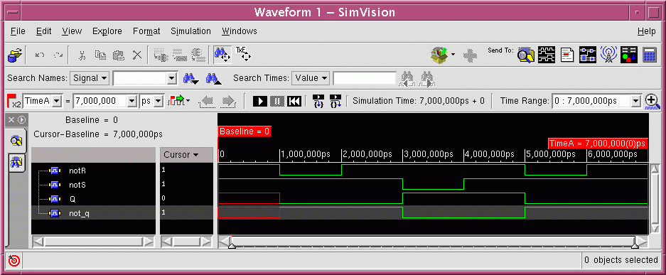
Note that screen captures of waveform windows such as the one above should never be used in a report because the black background obscures the waves while the window border and buttons distract from the information that you are trying to present.
Create a PDF copy of waveform display
First use the SimVision print window dialogue to create a PostScript (.ps) version of the waveforms. The print window dialogue is accessed from the File menu of the waveform window:
    File -> Print Window...

      Print
        Printer
          [Print to file:  -]   [ <printfile>.ps  ]
        Print Paper
          Paper Size: [ A4 (210mm x 297mm)    ]
      OK
Now convert the PostScript file to PDF using the ps2pdf unix command:
ps2pdf <printfile>.ps
Check that the file has been correctly generated using the evince document viewer:
evince <printfile>.pdf &
This PDF file can then be included in a report or printed directly to the printer.
Print a copy of the waveform
lp -d <printername> <printfile>.pdf
If you have problems printing directly to the printer, you may have to use the iSolutions provided print script which will prompt for a password before submitting the print job:
print -d <printername> <printfile>.pdf
To exit the simulator select Exit SimVision from the File menu:
File -> Exit SimVision
Where you wish to run simulations repeatedly (e.g. during development) or offer another user the chance to reproduce your simulations, a SimVision command script will save a lot of time.
The following file, rs_flipflop.tcl, is a simple SimVision script file for the RS flip-flop:
# SimVision command script rs_flipflop.tcl

simvision {

  # Open new waveform window

    window new WaveWindow  -name  "Waves for RS flipflop"
    waveform  using  "Waves for RS flipflop"

  # Probe primary I/O

    waveform  add  -signals  rs_flipflop_stim.notR
    waveform  add  -signals  rs_flipflop_stim.notS
    waveform  add  -signals  rs_flipflop_stim.Q

  # Probe internal signal

    waveform  add  -signals  rs_flipflop_stim.rs_instance1.not_q

}
Download the rs_flipflop.tcl command script and re-run the simulation including the +tcl option:
xmverilog +gui +access+r rs_flipflop_stim1.sv rs_flipflop.sv +tcl+rs_flipflop.tcl &
Then run the simulation (![]()
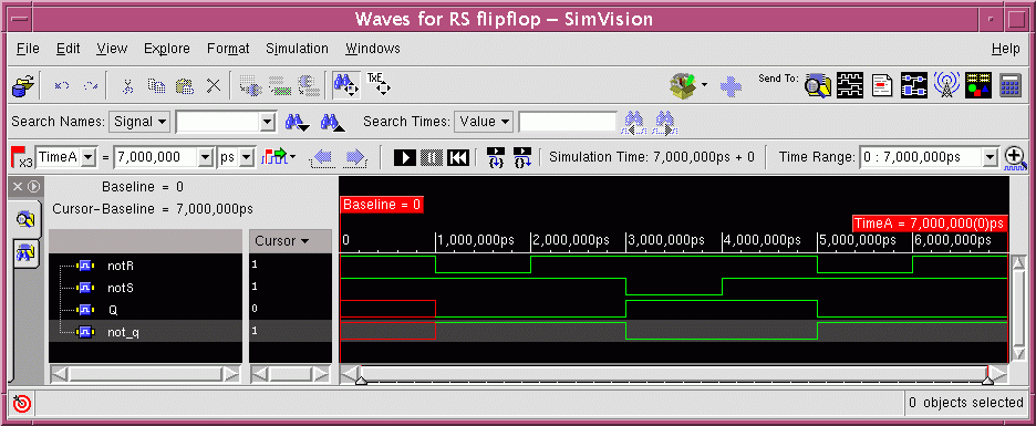
![]() ). The result is as before except that
the waveform window has the name given to it in the command script:
). The result is as before except that
the waveform window has the name given to it in the command script:
If you forget to use the +tcl option when you run the simulation, you can load the command script once SimVision is running:
    File -> Source Command Script...

      Source Command Script

        Filename:         [ rs_flipflop.tcl               ]

        Send commands to: [ simulator Console (XM-Sim)  - ]

      OK
this facility is very useful when developing command scripts.
You can write your own command script provided that you understand the naming convention for the signals. Each signal name is qualified by it's scope (i.e. the hierarchical name of the module in which the signal exists). Thus "rs_flipflop_stim.rs_instance1.not_q" refers to a signal named "not_q" within a module with instance name "rs_instance1" within the top level module "rs_flipflop_stim".
Note that signals which connect to module ports (inputs and outputs) can have multiple names since they have different names in the parent and child scope. Thus in this example, "rs_flipflop_stim.rs_instance1.q" is an alias for the signal "rs_flipflop_stim.Q".
Edit the stimulus file "rs_flipflop_stim1.sv" and add a statement "$stop;" just before the "$finish;" statement (this will prevent the modelsim simulation from terminating before you have looked at the waveforms).
if using nedit to edit files, you may need to add an import option on first use, in order to get correct highlighting of SystemVerilog syntax:
nedit -import /opt/cad/bim/nedit/systemverilog.pats rs_flipflop_stim1.sv &you should then save the default settings so that nedit remembers the syntax rules:
    Preferences -> Save Defaults...
    OK
Run the command
modelsim rs_flipflop_stim1.sv rs_flipflop.sv &
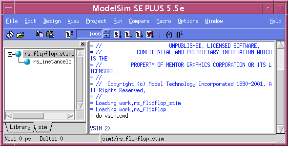
The behaviour of ModelSim is very similar to that of Xceliumin that it compiles the modules and then opens the the ModelSim GUI "Main Window":
As with Xcelium, the display of waveforms may be controlled either via selecting instances and signals and sending them to a waveform window or via a command script.
The following file, rs_flipflop.vsim, is a simple ModelSim script file for the RS flip-flop:
# ModelSim command script rs_flipflop.vsim

# Open new waveform window

  view wave -undock

# Probe primary I/O

  add wave -label "notR" notR
  add wave -label "notS" notS
  add wave -label "Q" Q

# Probe internal signal

  add wave -label "not_q" rs_instance1/not_q
Download the rs_flipflop.vsim command script and then execute it by typing "source rs_flipflop.vsim" at the "VSIM >" prompt in the ModelSim main window.
Then run the simulation either by typing "run -all"
at the "VSIM >" prompt or by selecting the
run -all icon, ![]() .
.
In order to see the full waveforms you will need to select
View -> Zoom -> Zoom Full from the pull down menus
of the wave window or select the zoom full icon,
![]() .
.
The resulting waveform window should look something like this:
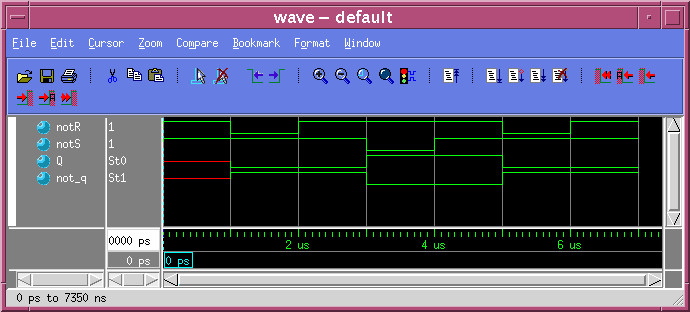
To print the waveform you will need to go through the same procedure of creating a Postscript file, converting it to PDF and then printing the PDF file. To create the PostScript file from ModelSim, invoke the Print Postscript dialogue from the Waveform window File menu:
    File -> Print Postscript...

      Write Postscript
        Printer
          [x] File name: [ <printfile>.ps  ]
      [OK]
If you have problems printing you may need to check that the page size is correctly set up File -> Page Setup... (either "A4 Sheet" or "A4 small sheet" should work).
You can then terminate the simulation by typing the following command in the main ModelSim window:
quit
To illustrate further functionality we will consider the simulation of a simple up/down counter:
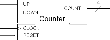 |
The SystemVerilog HDL model file for this circuit is up_down_count.sv. |
The following file, up_down_count_stim.sv, is a stimulus file for the up/down counter:
//stimulus file for an up/down counter

module up_down_count_stim;

timeunit 1ns; timeprecision 10ps;

logic Up, Down, nReset, Clock;
wire [3:0] Count;

  up_down_count instance1 ( Count, Up, Down, Clock, nReset );

  // stimulus information

  always
    begin
           Clock = 0;
      #250 Clock = 1;
      #500 Clock = 0;
      #250 Clock = 0;
    end

  initial
    begin
        nReset = 1;
        Up = 0; Down = 0;
      #1000
        nReset = 0;
      #1000
        nReset = 1;
      #1000
        Up = 1;
      #15000
        Up = 0;
      #1000
        $stop;
        Down = 1;
      #15000
        Down = 0;
      #2000
        $stop;
        Up = 1; Down = 0;
      #4000
        Up = 0; Down = 1;
      #7000
        Up = 1; Down = 0;
      #23000
        $stop;
        $finish;
    end


  // status interpretation

  function [5:0][7:0] get_direction(input up, down);
    if ({up,down} == 2'b10) return "Up";
    else if ({up,down} == 2'b01) return "Down";
    else if ({up,down} == 2'b11) return "Reset";
    else return "Hold";
  endfunction

  wire [5:0][7:0] direction;
  assign direction = get_direction(Up,Down);


endmodule
Here an "always begin end" construct is used to create a repetitive clock with a cycle time of 1000 nanoseconds. The "initial begin end" construct is used for changes in the stimulus signals which don't repeat.
The status interpretation section introduces two new concepts; the first is the declaration of a function and the second is the interpretation of a multibit value as a string. The result is a simulation that not only reports the state of the system but is also able to interpret the results it gets - it knows whether the counter is counting up or down and tells us so.
Note that the "wire [5:0][7:0]" declaration is creating a bus with enough bits to store a 6 character string where each charater is an 8 bit ASCII value.
The following file, up_down_count.tcl, is a SimVision script file for the up/down counter:
# SimVision command script up_down_count.tcl

simvision {

 # =========================================================================
 # Wave Window

  # Open new waveform window

    window new WaveWindow  -name  "Waves for Up/Down Counter"
    window  geometry  "Waves for Up/Down Counter"  1010x410+0+25
    waveform  using  "Waves for Up/Down Counter"

  # Add basic signals to wave window

    waveform  add  -signals  up_down_count_stim.Clock
    waveform  add  -signals  up_down_count_stim.nReset
    waveform  add  -signals  up_down_count_stim.Up
    waveform  add  -signals  up_down_count_stim.Down

  # Add Count signals to wave window (and remember wave the id)

    set id [waveform add -signals up_down_count_stim.Count]

  # Set radix for Count waveform to decimal

    waveform format $id -radix %d

  # Expand Count waveform

    waveform hierarchy expand $id

 # =========================================================================
 # Register Window

  # Open new register window

    window new RegisterWindow  -name  "Registers for Up/Down Counter"
    window  geometry  "Registers for Up/Down Counter"  460x275+0+500
    register  using  "Registers for Up/Down Counter"

  # Add signals to regs window (default loaction and format)

    register add up_down_count_stim.Up
    register add up_down_count_stim.Down

  # Add signal values (specified location and format)

    register addtype -type signalvalue -x0 250 -y0 30 -radix %s \
      up_down_count_stim.direction
    register addtype -type signalvalue -x0 250 -y0 50 -radix %b \
      up_down_count_stim.Count
    register addtype -type signalvalue -x0 250 -y0 70 -radix %d \
      up_down_count_stim.Count
    register addtype -type signalvalue -x0 250 -y0 90 -radix %x \
      up_down_count_stim.Count

  # Add shapes and text to regs window

    register addtype -type rectangle -x0 100 -y0 20 -x1 300 -y1 105 \
      -outline green
    register addtype -type line -x0 105 -y0 45 -x1 295 -y1 45 \
      -outline red

    register addtype -type text -x0 110 -y0 30 -text {Direction of count}
    register addtype -type text -x0 110 -y0 50 -text {Count (binary)}
    register addtype -type text -x0 110 -y0 70 -text {Count (decimal)}
    register addtype -type text -x0 110 -y0 90 -text {Count (hexadecimal)}

}


# =========================================================================
# Probe

  # Any signals included in register window but not in waveform window
  # should be probed

  probe -create -shm up_down_count_stim.direction

# =========================================================================
xmverilog +gui +access+r up_down_count_stim.sv up_down_count.sv +tcl+up_down_count.tcl &
In addition to the already introduced "window new WaveWindow", "waveform using" and "waveform add" instructions, this command script includes "waveform format" and "waveform hierarchy expand" commands.
The "waveform format" command is used to set the format of the presentation of the "Count" bus signal. In this case the radix selected is "%d" (decimal). Other supported radicies include "%b" (binary) and "%x" (hexadecimal).
The "waveform hierarchy expand" command allows us to see the individual signals within the "Count" bus signal.
Note that the command script is written in the TCL programming language. The TCL variable, "id", is used to ensure that the two new commands act on the "Count" waveform rather than any other waveform.
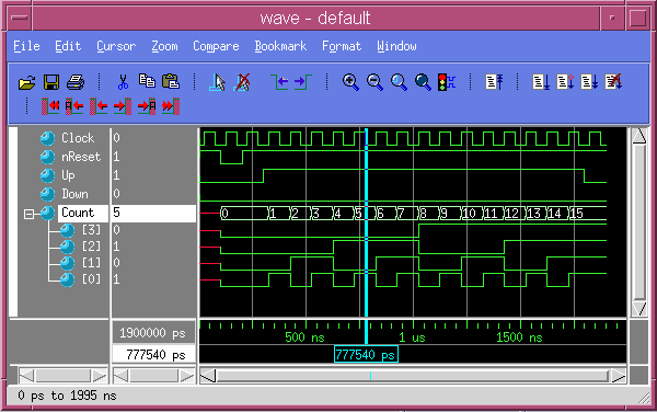
The decimal annotation of "Count" values and expanded "Count" bus can be seen in the resulting waveform display:
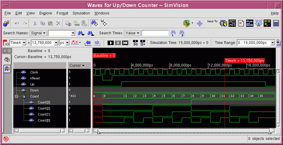
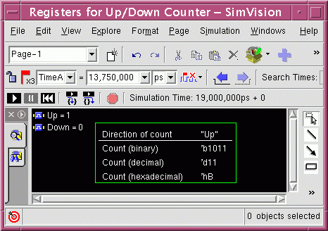
In the registers section of the command script, the new commands, "window new RegisterWindow" and "register using", are used to open a register window. This window will show a snapshot of system state at a particular time.
The "register add" commands are similar to the "waveform add" commands previously encountered in that they simply specify signals to be sent to the appropriate window.
In the top left of the registers window you will see the status of the "Up" and "Down" signals as a result of these commands:

The registers window also offers more advanced techniques for visualising the state of the system using different variants of the "register addtype" command.
With the "-signalvalue" option, the command allows signal values to be placed in specific locations in the window and also allows the format of display to be controlled. The "%s" radix specifier is used for the "direction" signal bus. It causes the bus to be interpreted as a character string.
The remaining "register addtype" commands allow rectangles, lines and text to be added to the picture to help with the presentation of results.
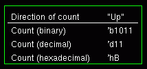
The final section of the command script includes a probe command for the "direction" signal. Any signal included in the Wave window is automatically probed, allowing its history to be recorded during the simulation so that you can review the results at the end. Signals such as "direction" which are included in the Register window but not in the Wave window are not automatically probed. They must be explicitly probed in order to be able to review the signal history at the end of the simulation.
Note that the "probe" command occurs after the "simvsion {....}" which surrounds all of the other commands. This is because "probe" is a simulation command for Xcelium rather than a command for the SimVision GUI.
For small designs an alternative "probe" command may be used:
probe -create -depth all -shm up_down_count_stimThis command will probe all signals within the design thereby avoiding the need to specify the signals individually. Since data must be stored for all probed signals, this approach may lead to very large simulation databases in larger designs.
The complete Register window is shown below:
These commands represent a small fraction of those available within SimVision. The SimVision on-line help (accessible via the Help mernu on any SimVision window) is a source of information about the use of the GUI and the commands that can be used in SimVision scripts.
The same primary time cursor, TimeA, is used in both the Wave window and the Register Window. As a result, when the cursor in the Wave window is moved, the values in the Register window will change to remain synchronized.
Since the stimulus section contains several $stop; statements
each of which is a simulation breakpoint, it is necessary to advance
the simulation several times to reach the end of the stimulus.
Simply select the play icon, ![]() , to
advance from one breakpoint to the next.
, to
advance from one breakpoint to the next.
The following file, up_down_count.vsim, is a ModelSim script file for the up/down counter:
# =========================================================================
# ModelSim command script up_down_count.vsim

# =========================================================================
# Wave Window

  # Open new waveform window

    view wave -undock

  # Add signals to wave window

    add wave -label "Clock"                   Clock
    add wave -label "nReset"                  nReset
    add wave -label "Up"                      Up
    add wave -label "Down"                    Down
    add wave -label "Count" -unsigned -expand Count

# =========================================================================
# List Window

  # Open new list window

    view list -x 0 -width 400

  # Add signals to list window

    # first set a default radix without the "-showbase" option
    # (this seems to overcome a bug in the list display)
    radix -hexadecimal

    add list -label "Direction of count"  -ascii       direction
    add list -label "Count (hexadecimal)" -hexadecimal Count
    add list -label "Count (decimal)"     -unsigned    Count
    add list -label "Count (binary)"      -binary      Count
modelsim up_down_count_stim.sv up_down_count.sv &
Then source the command script up_down_count.vsim.
The "add wave" command allows us to simply specify the format for bus signals:
| -unsigned | gives unsigned decimal format |
| -signed or -decimal | gives signed decimal format |
| -binary | gives unsigned binary format |
| -hexadecimal | gives unsigned hexadecimal format |
| -ascii | gives ASCII string format |
In addition, the -expand option allows us to view individual bus signals.
The result is very similar to the SimVision wave window:
The nearest that ModelSim has to a register window is provided by the "view list" and "add list" commands which provide a graphically enhanced $monitor(); type facility.
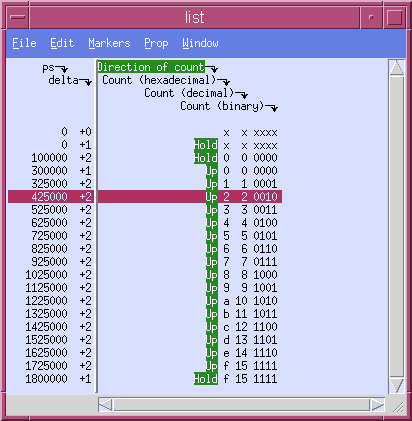
In this case to advance from one $stop; to the next, type
run -allin the main ModelSim window or select the appropiate icon,
Continuing beyond the last $stop; will take you to a $finish; statement in the stimulus file thereby terminating the simulation.
In this lab you should have seen the Xcelium and ModelSim simulators in GUI and batch mode versions.
N.B. In general, GUI simulations are used in development, while batch mode simulations are used for verification against known functionality. For example, when students submit designs for marking, a batch mode simulation will be run and should give a simple pass/fail result without having to study waveforms.
All SystemVerilog and Verilog documentation is available on-line via Cadence Help. Type the following at the unix command prompt in order to invoke Cadence Help:
cdnshelp -hierarchy /eda/cadence/xcelium &
On-line manuals of particular interest to this tutorial are:
Iain McNally
24-10-2023