Run the following sequence of instructions. If all goes well you will see two example processor simulations. The first using the behavioural model of control.sv in the behavioural directory and the second using the newly synthesized gate level model of control.sv in the gate_level directory.
mkdir -p ~/design/synth/ex_control cd ~/design/synth/ex_control init_fcde_example behavioural ./simulate behavioural cp -pr behavioural gate_level rm gate_level/control.sv genus_custom -batch -pkg behavioural/opcodes.svh behavioural/control.sv gate_level/control.sv cp -p /opt/cad/bim/fcde/svfiles/no_state_view/system.fig gate_level/ ./simulate -gate gate_level +define+no_state_viewNote that the new system.fig file from the no_state_view directory and the +define+no_state_view option for simulation are a "quick and dirty" way of ensuring that the simulation is not dependent on the names of the state signals inside the control module (since the these names change as a result of the synthesis process). A neater way to solve the problem is to edit gate_level/monitor.sv and gate_level/system.fig so that they use the new signal names created by the synthesis tool.
For more details on the use of Genus synthesis for synthesis see this lab.
Alternatively you can use Synopsys Design Compiler for synthesis in place of Cadence Genus synthesis. To do this, simply replace genus_custom in the command above with dc_custom (note that dc_custom may not work with all cell libraries - Synopsys Design Compiler is more fussy than Cadence Genus synthesis).
Run the following sequence of instructions in order to generate a default magic placement file control_PLACED.mag and a matching magic netlist file control_PLACED.net.
mkdir place_route cd place_route/ vlog2net -T tsmc180 -clocks ../gate_level/control.sv /opt/cad/bim/fcdeCells/magic/tsmc180/abstracts/cell_lib
Select the default response (press the return key) to all questions asked by the vlog2net program.
Open the control_PLACED.mag file using magic:
magic control_PLACED
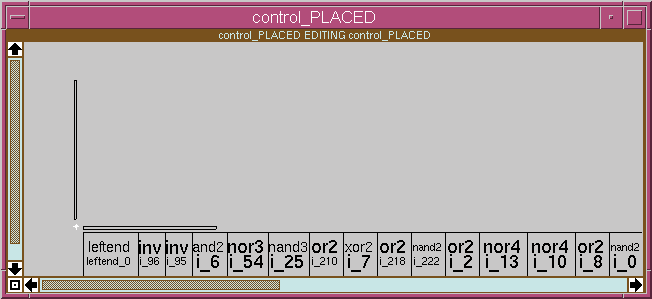
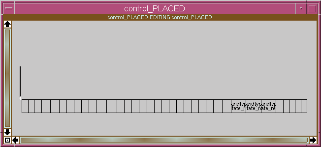
This magic cell includes a row of leaf cells along the bottom of the design and a single terminal cell on the left. The terminal cell, named control_TERM_L, contains the port labels for the final design. The resulting window should look something like this:
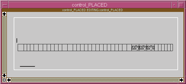
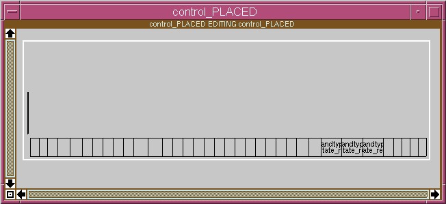
Use the magic box tool to define the routing area. The area defined should extend significantly above the row of leaf cells and the terminal cell. If you define the routing area too small, the routing will fail. The resulting window should look something like this:
Execute the routing command within magic:
:route
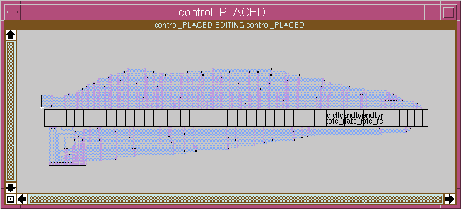
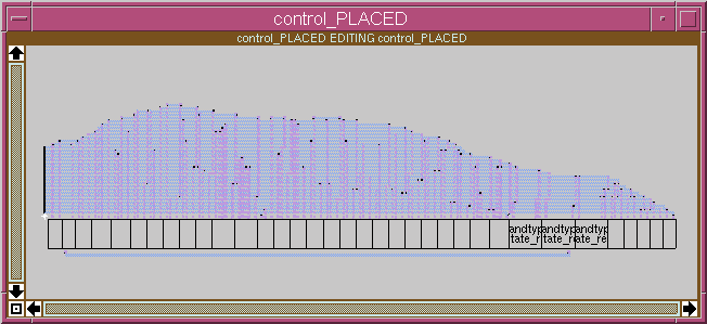
The resulting window should look something like this:
Now open the netlist menu window:
:specialopen netlist
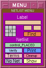
and click the Verify netlist button to check that all nets are correctly routed and that no short circuits have been accidentally created.
If you are planning on using this facility for your own designs you will have to read the magic tutorial on netlists and routing which gives much more information than can be included in this walkthough.
Save the resulting cell and quit magic.
Run the following command to post process the control_PLACED.mag file to produce control_ROUTED.mag which has i/o instances removed:
vlog2net -T tsmc180 -post ../gate_level/control.sv /opt/cad/bim/fcdeCells/magic/tsmc180/abstracts/cell_lib
Open the control_ROUTED.mag file using magic:
magic control_ROUTED
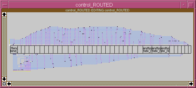
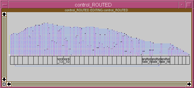
The resulting window should look something like this (note the yellow labels on the left hand side where the control_TERM_L cell used to be):
The first cycle of Place & Route used:
The second cycle we will use:
The new vlog2net command includes the -f option to force the regeneration of the default i/o configuration file (control_IO.cfg):
vlog2net -T tsmc180 -fcde -f ../gate_level/control.sv /opt/cad/bim/fcdeCells/magic/tsmc180/abstracts/cell_lib
VPORT LEFT input Opcode[3:0] PORT LEFT input Zflag PORT LEFT input nWait PORT LEFT input Clock PORT LEFT input nReset VPORT LEFT output Function[3:0] PORT LEFT output SelInc PORT LEFT output LoadPC PORT LEFT output LoadIR PORT LEFT output TrisOperand PORT LEFT output TrisPC PORT LEFT output TrisAcc PORT LEFT output TrisMem PORT LEFT output ENB PORT LEFT output nME PORT LEFT output ALE PORT LEFT output RnW PORT LEFT output nOE PORT LEFT input Test PORT LEFT input SDI PORT LEFT output SDOAfter editing, the file should look like this:
# Left connections to pad ring PORT LEFT output SDO PORT LEFT output RnW PORT LEFT output nOE PORT LEFT input nWait PORT LEFT output nME PORT LEFT output ALE PORT LEFT output ENB # Bottom connections for system signals PORT BOTTOM input SDI PORT BOTTOM input Test PORT BOTTOM input Clock PORT BOTTOM input nReset # Bottom connections for signals to/from datapath VPORT BOTTOM output Function[3:0] PORT BOTTOM output SelInc PORT BOTTOM output LoadPC PORT BOTTOM output LoadIR PORT BOTTOM output TrisOperand PORT BOTTOM output TrisPC PORT BOTTOM output TrisAcc PORT BOTTOM output TrisMem VPORT BOTTOM input Opcode[3:0] PORT BOTTOM input Zflag
Zooming in on the left hand end of the design you can see the two terminal cells: control_TERM_B (with instance name TERMINALS_B for the bottom terminals) and control_TERM_L (with instance name TERMINALS_L for the left terminals).
These terminal cells need to be placed appropriately around the edges of the design. The following magic commands will move the TERMINALS_B instance to a suitable location at the bottom of the design leaving space for routing:
:select cell TERMINALS_B :move down 1000 :move right 132
Selecting a suitable space with the box tool, the cell looks like this before routing:
and like this after routing and verification:
Save the design and quit magic.
The result should look something like this:
So far, all the designs have used magic cells from the directory:
/opt/cad/bim/fcdeCells/magic/tsmc180/abstracts/cell_lib
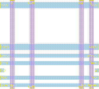
These cells are merely abstracts, with correctly labelled ports but containing no transistors, as can be seen from this picture of the scanreg cell:
If you have read and understood the magic tutorial on netlists and routing then you are now in a position to try and use your own cell library. Automated routing with your cells will be harder if they have not been designed on a strict 0.66 micron grid (unlike the abstract cells). The router will make mistakes and you will have to edit the resulting magic design, firstly to correct routing errors and subsequently to remove design rule errors.
Run the command below to place and route cells from your own cell library:
vlog2net -T tsmc180 -fcde ../gate_level/control.sv ~/design/magic/tsmc180/cell_libNote that in this case the -fcde option is selected so your cell library will have to include leftbuf and rightend cells. Note also that the -f option has not been used so the program will re-use the old i/o configuration file: control_IO.cfg which was created during walkthough 2.
If your own ports are offset from the 0.66 micron grid, you can add an extra option e.g. "-offset 8" to the "vlog2net" command.
During the operation of this command you will see a new prompt asking you if you wish to overwrite path in existing .magic file. You should accept the default which is to overwrite the old value.
When you come to the routing stage you should use the information you have gained from the magic tutorial on netlists and routing to correct any routing errors and verify the final routing.
Note that the message "No routing errors" is often given inappropriately. In particular nodes shorted by the :route command are not detected until the netlist is verified. As in the first walkthrough, verification is achieved by clicking the Verify button in the netlist menu window. Where problems are highlighted you can use the :feedback find and :findbox zoom commands to track down the "feedback" markers left by the verification. You may also find the :findlabel <lab> command useful at this time.
Although there is no need to correct DRC errors for this walkthough, all routing errors should be corrected before you go any further. After making modifications you should clear all "feedback" markers using the :feedback clear command before re-verification.
When eventually you are prompted about creation of an extracted verilog file you should accept and then use the extracted file in a full simulation of the example processor.
Here is a quick summary of the appropriate commands
cd ~/design/synth/ex_control cp -pr gate_level extracted rm extracted/control.sv cd extracted ln -s ../place_route/control.sv ln -s ../place_route/control.vnet nedit cpu_core.sv
In the nedit window you will need to modify the scan path routing for the processor since the control unit now has ports for Test, SDI and SDO. Since the datapath does not yet have a scan path, all you need to do is remove the "assign SDO = SDI;" statement and add "Test, SDI, SDO" to the end of the Control instance port list.
Note that this edit relies on the port order for the extracted control module
being the same as that for the behavioural control module.
It is much safer to use port connection by name such as
used in this example file:
cpu_core.sv
This will also need editing as this version assumes that both the
datapath and the control unit support a scan path.
Having edited cpu_core.sv you can run the extracted simulation:
cd ~/design/synth/ex_control ./simulate extracted +define+no_state_viewOnly if this works should you consider the final walkthough.
Here you will need to repeat the synthesis step for your control unit. You can then go on to perform a new place and route:
vlog2net -T tsmc180 -fcde -f ../gate_level/control.sv ~/design/magic/tsmc180/cell_lib
Here the -f option is used to regenerate a default control_IO.cfg file which you should customize to match the order of connections along the top of your datapath (The ordering of PORT lines in the control_IO.cfg file determines the left to right ordering of the i/o ports across the bottom of the final cell). Ideally you will want to edit the control_TERM_B cell before routing, such that it matches exactly the location of the connections along the top of the datapath.
Hint: Don't attempt to correct DRC errors until you are sure that everything else is right. Any time you re-run the routing algorithm all work on DRC errors is lost.
Iain McNally
20-12-2018